Understanding Walk-In Cooler Refrigeration System Components and Their Functionality
Understanding Walk-In Cooler Refrigeration System Diagrams
A walk-in cooler is an essential component for businesses that require reliable refrigeration for perishable goods. Understanding the refrigeration system diagram for a walk-in cooler is crucial for efficient operation, troubleshooting, and maintenance. This article delves into the components of walk-in cooler refrigeration systems, their functions, and the significance of each element in the diagram.
At its core, a walk-in cooler refrigeration system operates on the principle of heat transfer, utilizing a refrigerant in a closed loop to absorb heat from the cooler interior and expel it outside. The primary components typically depicted in a refrigeration system diagram include the compressor, condenser, expansion valve, and evaporator.
1. Compressor The compressor is often considered the heart of the refrigeration cycle. It is responsible for compressing the refrigerant gas, raising its pressure and temperature. The high-pressure gas then flows to the condenser. In the diagram, the compressor is usually shown at the top, connected to both the condenser and evaporator.
2. Condenser Located outside the cooler, the condenser's primary role is to dissipate heat absorbed by the refrigerant. As the refrigerant passes through the condenser coils, it cools and transforms back into a liquid state. The heat removal process is typically enhanced by airflow or water cooling, which can be represented in the diagram with fan symbols indicating airflow direction or water lines for water-cooled systems.
walk in cooler refrigeration system diagram
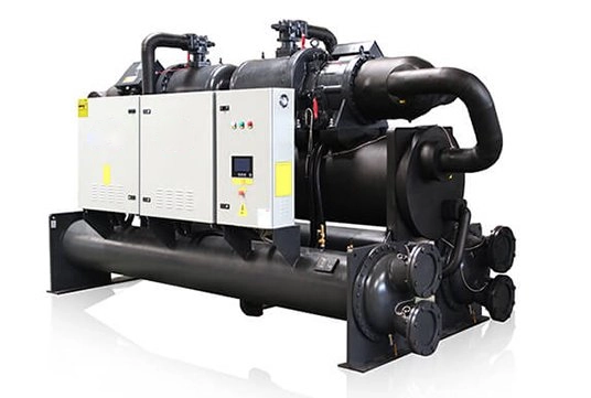
3. Expansion Valve After passing through the condenser, the high-pressure liquid refrigerant enters the expansion valve. This component serves to reduce the pressure of the refrigerant, causing it to expand and cool significantly. In the system diagram, the expansion valve is often depicted as a restrictor or a capillary tube that shows the flow path leading to the evaporator.
4. Evaporator The evaporator is located inside the walk-in cooler and is responsible for absorbing heat from the cooler's interior. As the low-pressure liquid refrigerant enters the evaporator, it evaporates and absorbs heat, causing a drop in temperature inside the cooler. The evaporator coils are typically represented in the diagram with arrows indicating the airflow within the cooler, as fans help circulate the cold air.
5. Refrigerant The refrigerant, typically a hydrofluorocarbon (HFC), is a critical component that cycles through the system, undergoing phase changes to absorb and release heat. Diagrams often include lines indicating the flow of the refrigerant in both liquid and gas states, as well as pressure and temperature indicators at various points in the system.
Understanding these components and their functions is crucial for anyone involved in the maintenance or operation of walk-in cooler refrigeration systems. The diagram serves as a roadmap, guiding technicians in diagnosing issues such as inadequate cooling, refrigerant leaks, or mechanical failures.
In conclusion, a walk-in cooler refrigeration system diagram provides valuable insights into the operational dynamics of the cooling cycle. Familiarity with components like the compressor, condenser, expansion valve, and evaporator helps ensure that the system runs efficiently. Proper understanding and maintenance of these systems not only enhance food safety and preservation but also contribute to energy efficiency, ultimately benefiting businesses and consumers alike.


